
2d model ball mills manufacturer Grasping strong production capability, advanced research strength and excellent service, Shanghai 2d model ball mills supplier create the value and bring values to all of customers.
 WhatsApp)
Charge shape and trajectory in the 2D model mill. In order to determine the endwall effect in the 2D model (, short length) mill at different operating conditions, a 100 cm × cm mill was used. As the mill rotates the charge is lifted up with the rising face of the mill until the shoulder is reached.
.(Conical Ball) Router Bits with special unique carbide with nACo nanocomposite coating for longer designed for 2D and 3D CNC profiling and carving in plastic wood with machines with CNC machines. The highshear ball nose tips cut smooth 2D and 3D contours with reduced stepping.
For example, using a 2flute, .250" ball end mill at 980 sfm with a .002" ipt chip load, and a .020" DOC (axial and radial): When the endmill is parallel to the surface (cutting with the side), I get a 15,000 rpm spindle speed, and 111 ipm feed rate.
This work develops a mathematical model that explains the ball mills operational speed. The scope of the model is defined by the powder as the number of particles per cm3 and the Relevance defined as the ratio between different forces. In this study, the Relevance is defined as the ratio between superficial tension and inertial forces. The conditions for a free flowing powder and a single ...
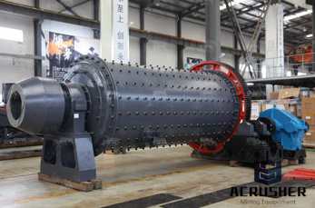
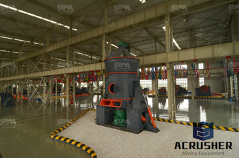
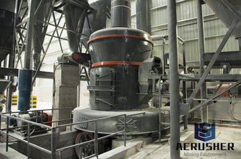
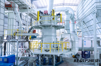
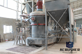
Ball Mills are generally used to grind material 1/4 inch and finer, down to the particle size of 20 to 75 microns. To achieve a reasonable efficiency with ball mills, they must be operated in a closed system, with oversize material continuously being recirculated back into the mill to be reduced.
ball mill all models of ball mill. Every Day new 3D Models from all over the World. Click to find the best Results for ball mill Models for your 3D Printer. ball mill modeling miningbmw. Learn More; ball mill 3d model solidworks – Grinding Mill China. ball mill SOLIDWORKS 3D CAD model GrabCAD. ball mill ball mill for ore ginding ...
the mill is used primarily to lift the load (medium and charge). Additional power is required to keep the mill rotating. Power drawn by ball, semiautogenous and autogenous mills A simplified picture of the mill load is shown in Figure Ad this can be used to establish the essential features of a model for mill .
(2D) or spherical (3D) particles. Model of media motion states According to the geometric parameters of ball mill and the contact parameters between particles, the program is compiled and merged to simulation software. Then the simulation model of ball mill shell is established. The rotating velocity of the mill in cascading or cataracting ...
FINITE ELEMENT MODEL Figure 1 shows apparatus for the experimental approach that previously performed by using two flute ball end mill by Yassin et al. [19]. This apparatus were then being modeled to 2D finite element model as shown in Figure 2. 10µm tool edge radius, r were used according to original cutting tool.
Ball Mill Solidworks X Ball Mill D Model Solidworks. Ball Mill 3d Model Solidworks Apponaug Christian . modeling ball end mill in solidworks. ball mill SOLIDWORKS 3D CAD model, Nov, was used for discrete element modeling of the ball mill, That way it can be cut in with a ball end mill quickly.
The earliest DEM model of a ball mill was in 2D by Mishra and Rajamani, . This was followed by Cleary, and then Cleary and Sawley . Then Mishra, provided a review on DEM, its use of contact models and appliion to tumbling mills in general. Ball Nose (Conical Ball) Solid Carbide Spiral CNC 2D/3D .
Radius milling uses a 2D Contourlike toolpath to produce an external fillet. Using the 2D toolpath requires a Radius Mill, but you can accomplish similar results with a Ball Mill and 3D contour toolpath. 8 – Spot Drilling . You can use center drilling to create a conical shape on the face of your part.
Jun 14, 2018· That was my comment that an endmill wasn''t the plan but was close enough to show the concept. A radiused cutter was the plan but the endmill caused enough pain to model in. A ballnose cutter would require a lot more cuts than the single U shaped path. This model was just an example to illustrate the difficulties in modelling cutter paths.
Nov 12, 2014· 3D Animation Demo working site of Ball Mill Henan Bailing. Loading... Unsubscribe from Henan Bailing? Cancel Unsubscribe. Working... Subscribe Subscribed Unsubscribe
I''ve been trying to model cut produced by a ball end mill taking an arbitrary 3D path. I know how to do this for 2D paths (and this has been discussed a couple of times on this forum), but I have had little to no success extending this to paths in 3D. I''ve attached an Inventor file that demonstrates ...
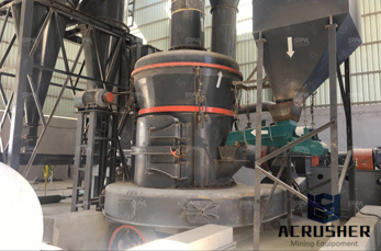
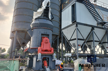
A Ball Mill is an industrial equipment used to grind different materials using steel (usually) spheres to schock with the material and cause it to reduce its size . ... 3D Model. Ball Mill Giovanni C. 0 Likes | 102 Downloads | 212 Views Download. Description. A Ball Mill is an industrial equipment used to grind different materials using steel ...
ball mill for ore ginding. The ComputerAided Design ("CAD") files and all associated content posted to this website are created, uploaded, managed and owned by third party users.
Portable Ball Mill Turnion Lathe 3D CAD model GrabCAD. May 11, 2015 . This is portable lathe for machining worn diameters on operationally damaged ball mill trunnions up to 2m diameter and 900mm axial length, w. >More
3d model of ball mill trunnion bearing. Get More Nov 13, 2016 · Alumina Ball Mill Maintenance ball mill foundation drawing pdf Australia. ball mill bearing ball mills shop drawings of different sizes and capacity draw plan grinding mill cad england aoes. grinding ball.
Jun 06, 2014· What is the best way to model a ball end mill feature? i know there must be many ways, what method do you use on flat surface. complex surface, and cylinder?? on top i used a simple 2D extrude cut with fillet on bottom, lower i used a swert cutbut not sure how to get the rounded start and end conditions ???
3d model of ball mill trunnion bearing model of ball mill trunnion bearing. Horizontal grinding mills SKF. SKF trunnion support housings. Two robust, double Vring seals keep lubricants in and Elimin
Jul 15, 2016· In this case, the second toolpath is a 2D Contour following the part''s bottom outline, using the same mill as the previous action. To keep the model locked in place until the end of the milling, you can enable the Tabs and choose their shape, thickness, and position. I set mine to triangular, 3mm wide, and with a thickness of
Jun 26, 2017· Ball Nose Milling Without a Tilt Angle. Ball nose end mills are ideal for machining 3dimensional contour shapes typically found in the mold and die industry, the manufacturing of turbine blades, and fulfilling general part radius properly employ a ball nose end mill (with no tilt angle) and gain the optimal tool life and part finish, follow the 2step process below (see Figure 1).
ball mill 3d model 3d model of ball mill trunnion bearing. 3d model of ball mill trunnion bearing. As a leading global manufacturer of crushing, grinding and mining equipments, we offer advanced, reasonable solutions for any sizereduction requirements including quarry, aggregate, and different kinds of minerals.
WhatsApp)