
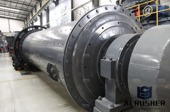
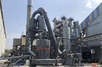
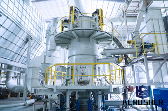
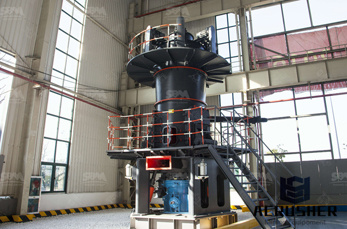
pi d symbols of chemical apparatus and equipment manufacturer Grasping strong production capability, advanced research strength and excellent service, Shanghai pi d symbols of chemical apparatus and equipment supplier create the value and bring values to all of customers.
 WhatsApp)
Process flow diagrams (PFDs) are used in chemical and process engineering. These diagrams show the flow of chemicals and the equipment involved in the process. Generally, a Process Flow Diagram shows only the major equipment and doesn''t show details. PFDs are used for visitor information and new employee training.
Aug 20, 2017· It is not drawn to scale and hence geometric accuracy can not be expected out of PID. PID Symbols. The instrumentation symbols used in PID are as per standard – Instrumentation Symbols and Identification. For Symbols of chemical apparatus and equipment normally ISO, JIS, DIN or PIP standards are followed.
This science ClipArt gallery offers 206 illustrations of equipment and apparatus used in chemistry experiments and procedures, and includes images of full apparatus as well as parts, such as lab beakers and flasks. See also the Balances gallery in the Simple Machines collection.
Piping and Instrumentation Diagrams (PIDs) use specific symbols to show the connectivity of equipment, sensors, and valves in a control system. These symbols can represent actuators, sensors, and controllers and may be apparent in most, if not all, system diagrams.
Dec 21, 2017· PIDs (Piping Instrumentation Diagrams) and PID Valve Symbol Library Posted on December 21, 2017 by Jeff_Rinker A piping and instrumentation diagram (PID) is a graphic representation of a process system that includes the piping, vessels, control valves, instrumentation, and other process components and equipment in the system.
Although standards are periodically revised, the continuous introduction of an increasing variety of chemical plant equipment results in a timelag in the formulation of acceptable symbols. The British StandardsInstitution has recently published BS 1553: Part 1 : 1977 Graphical symbols for general engineering: piping systems and plant.
• Graphical description of the process and process equipmentGraphical description of the process and process equipment using standard symbols (ANSI/ Instrumentation Symbols and Identification) • The PID is used by field technicians, engineers and operators to better understand the process and how the instrumentation is interconnected.
Piping and Instrumentation Diagram Documentation Criteria April 2008 1. Introduction Purpose This Practice provides requirements for designers preparing Piping and Instrumentation Diagrams (PIDs). Scope This Practice describes the requirements for PID format and content. The Practice is
Symbols used in Process Flow Diagram (PFD) or Process Flow Scheme (PFS) Piping Instrument Diagram (PID) or Process Flow Engineering Scheme (PEFS) Process Instrument Diagram Visit Today
how to interpret symbols of chemical apparatus and equipment. pi d symbols of chemical apparatus and equipment. pi d symbols of chemical apparatus and equipment Process Control The following safety and common symbols may be used in this manual and on the equipment Symbol. Get price.
Custom symbol or code 4 PID Requirements Introduction A PID shows information on piping, fittings, equipment, instrumentation, and process plant in a representative and sequential arrangement on the basis of product flow paths. The PID layout does not necessarily reflect physical arrangements. A PID is not drawn to scale.
how to interpret symbols of chemical apparatus and equipment. Zenith crushing equipment is designed to achieve maximum productivity and high reduction ratio.
Dec 07, 2012· Piping and instrumentation diagram – Wikipedia, the free . Symbols of chemical apparatus and are listed some symbols of chemical apparatus and equipment normally used in a PID, . »More detailed
The Piping and Instrument Diagram (PID), based on the Process Flow Diagram (PFD), represents the technical realization of a process by means of graphical symbols for equipment and piping together with graphical symbols for process measurement and control functions.
View Lab Report Symbols of chemical apparatus and equipment from CHEM ENGG 201 at University of Engineering Technology. Symbols of chemical apparatus and equipment.
Symbols of Equipment and Operating Conditions ... physical or chemical characteristics, is assembled or disassembled from another object or is arranged or prepared for another operation, transportation, inspection or storage. Jan. 1996
symbols for equipment and piping as well as graphical symbols for process measurement and control functions. The Utility Distribution Flow Diagram (UDFD) is a special type of a PID which represents the utility systems within a process plant showing all lines and other means required for the transport, distribution and collection of utilities.
JonnyRingo, first and foremost, loves to read and write. One of his specialities is writing on chemistry. The first and foremost rule of any laboratory is to be safe! This may seem obvious, but people often disregard safety protocols for one reason or another, putting themselves and those around ...
The vector stencils library "Industrial equipment" contains 81 symbols of pumps, compressors, fans, turbines, and power generators. Use these shapes to design pumping systems, air and fluid compression systems, and industrial process diagrams. "Process engineering focuses on the design, operation, control, and optimization of chemical, physical, and biological processes.
Piping and Instrumentation Diagram (PID) The piping and instrumentation diagram (PID), also known as mechanical flow diagram (MFD), provides information needed by engineers to begin planning for the construction of the plant. The PID includes every mechanical aspect of the plant except the information given in Table
Process equipment symbols are not part of this standard, but are included only to illustrate applications of instrumentation symbols. Application to industries The standard is suitable for use in the chemical, petroleum, power generation, air conditioning, metal refining, and numerous other, process industries.
For reference designation of any equipment in a power station the KKS Power Plant Classification System can be applied. Symbols of chemical apparatus and equipment. Below are listed some symbols of chemical apparatus and equipment normally used in a PID.
how to interpret symbols of chemical apparatus and equipment. pi d symbols of chemical apparatus and equipment. pi d symbols of chemical apparatus and equipment Process Control The following safety and common symbols may be used in this manual and on the equipment Symbol.
Sep 13, 2015· Process design for chemical engineers 1. Mahdi Khademi Fall 2015 2. Introduction Class Expectations To be able to provide a complete design package of a chemical plant and complete report Groups of maximum 4 students Project due on Dec 1st in electronic pdf format
WhatsApp)